Applications Engineering Department. Valley Fill Passive Power Factor Correction method or Valley Fill circuit is generally a circuit of two electrolytic capacitors a resistor and two diodes.

Valley Fill Circuit Semantic Scholar
The advantage of using a current fed resonant inverter in the proposed power circuit is that it provides isolation to the driver circuit without the use of any isolation devices.

. Published 8 years ago. 3 -50 Valley Fill Passive PFC Circuit Although the circuit presents a reasonably good Power Factor 095 and the harmonics can be tamed by the L-C input filter the major shortcoming of this circuit is the 50 bus ripple voltage which in a typical ballast circuit results in a. The proposed LED driver achieves high input power.
Observe how the ac supply current looks more sinusoidal that the other circuit I made to compare with rectifier no pfc which can only draw current when the dc side voltage is 2 diode drops. Passive Valley Fill Test Results with 36WT8 ballast section PIN 365W VAC 230V load. For example consider a 120-W PFC circuit operating from a 120-V line.
Figure 11 shows the complete CFL ballast design. The feasibility of the proposed charger has been verified with a 17-kW prototype. Power delivered to the load will have significant ripple at twice the line power frequency.
The amount of modulation frequency range can be adjusted by varying R6. Valley fill approach is added with LC 3 characteristics to further enhance the performance of the LC 3-based LED driver. Valley fill with passive PFC circuits B and active PFC shown C.
The valley-fill circuit is designated by the reference numeral 10 which includes a rectifying circuit 12 having input leads 14A and 14B tied to a power supply 4. However the peak charging current spike still persists. The Valley fill concept is applied to reduce the output voltage ripple of LED driver.
Harmonic Content of Valley-Fill with Voltage Doubler. Figure 7 shows the circuit with frequency modulation. We can call Valley Fill Passive Power Factor Correction method in easy term as Valley Fill Circuit.
The high-frequency peak current is twice that value so 28-Ap-p high frequency current flows into the PFC circuit. A 03 May 2013. Design LM3445 SNVS570MJANUARY 2009REVISED NOVEMBER 2015 LM3445 TRIAC Dimmable Offline LED Driver 1 Features 3 Description The LM3445 is an adaptive constant off-time ACDC 1 TRIAC Dim Decoder Circuit for LED Dimming buck step-down constant current controller designed.
The figure D are this novel PFC and regulation methodology. The solution under study is based on a DC to AC resonant inverter whose input voltage is taken from a valley-fill AC-DC passive converter. Electronic CFL ballast Circuit using.
Generally you would find higher ripple on a valley fill circuit vs a simple bridge-diode rectifier. Valley Fill Circuits Two Capacitor ValleyFill Three Capacitor ValleyFill While the valley-fill rectifier improves the utilization of the line current it does not provide a constant input to the switching regulator. The valley-fill circuit uses a single storage capacitor instead of two.
36WT8 and additional circuit to modulate the frequency. For low power applications theres a rectifier circuit known as a valley-fill rectifier. While the circuitry appears very simple the design of an effective correction system is actually.
Valley-Fill with Voltage Doubler Fig. Design Example Report. The ballast circuit is the combination of a valley fill circuit and a new frequency modulated current fed resonant inverter.
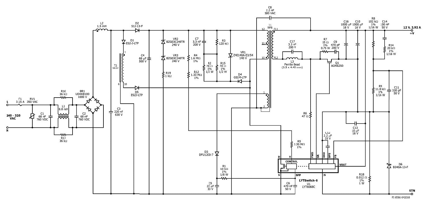
Valley-Fill PFC Circuit. 140 VAC 320 VAC Input. This paper presents the design and analysis of an integrated LC 3 Valley fill passive LED driver suitable for HBLEDs.
Emergency Light with Battery Charging. 120Vac Valley Fill Buck Triac Dimmable LED Driver. Passive Valley Fill circuit with frequency modulation.
The capacitor is charged to the maximum voltage of the AC cycle which increases energy storage density so that it is possible to use of low-capacitance high-voltage capacitors. AN-1656 Design Challenges of Switching LED Drivers Rev. Take better selfies with innovative LED flashes.
Current waveform of the passive PFC valley fill circuit. A new Circuit for Low-Cost Electronic Ballast Passive Valley Fill with Additional Control Circuits for Low Total Harmonic Distortion and Low Crest Factor on. Valley-Fill Circuit with Voltage Doubler Figures 5 shows the input current waveform with the improvements at the cross-over points and Figure 6 is the Fourier plot of the harmonics.
TM-6 LYT6068C Specification. The proposed charger is based on a diode-clamped series resonant converter equipped with a resonant valley-fill circuit which increases the power factor by removing dead zones in the line current and reduces the switching loss of the valley-fill circuit. The DC output of.
It is a passive power factor correction circuit I think I found it on Wikipedia. A diagram that uses lines to represent the wires and symbols to represent components. Its simple to implement but is only suitable where a very high effective ripple voltage on the DC output can be tolerated.
A valley-fill circuit has power factor correction circuit with active conduction angle control. The input nominal current would be about 1 A and the peak of the sine wave input current would be about 14 A. Electrician Circuit Drawings and Wiring Diagrams Youth Explore Trades Skills 3 Pictorial diagram.
Solving the automotive EMI issues in new cars with all the screens. A diagram that represents the elements of a system using abstract graphic drawings or realistic pictures. The intend of the Valley Fill Passive Power Factor Correction method is to let the power converter to pull power straight off the AC line.
12 V 292 A Output. Valley fill pfc it is possible to use a Valley Filler circuit to smooth the DC after a rectifier Not really valley fill if used to smooth the dc would use large capacitors and you would find power factor start to drop. Title 35 W High Power Factor Isolated Flyback with Switched Valley Fill PFC Power Supply Using LYTSwitch.
CVF1 DB3 LRES Fig11. This ballast includes AC input stage with EMI filter valley fill PFC stage ballast control stage using IR2520D adaptive ballast control IC and lamp current crest factor control circuit half-bridge inverter and resonant output stage. Derive raw dc voltage from the utility a line figure above.
A valley-fill circuit is a type of passive power factor correction PFC circuitFor purposes of illustration a basic full-wave diode-bridge rectifier is shown in the first stage which converts the AC input voltage to a DC voltage.

File Valley Fill Circuit Svg Wikimedia Commons

A Passive Driver Circuit With Valley Fill Circuit B Idealized Download Scientific Diagram
Proposed Valley Fill Power Factor Corrector Circuit Download Scientific Diagram

Valley Fill Circuit Wikipedia

Valley Fill Passive Power Factor Correction Method Power Electronics Talks
35w Isolated Flyback With Switched Valley Fill Pfc Reference Design New Industry Products

Low Cost Dimmable Led Ballast Using The Valley Fill Current Shaping Circuit
Valley Fill Circuit Wikipedia
0 comments
Post a Comment